

Top Cleanroom HVAC System Design Strategies for Precise Contamination Control
2026-08-25
Every particle, every pressure differential, every degree of temperature swing can decide whether a pharmaceutical batch survives or gets scrapped. Cleanroom HVAC design isn't just about moving air—it's about engineering certainty. At GENO Pharmatech, we've seen too many projects treat airflow as an afterthought, only to battle contamination breaches later. This guide breaks down the design strategies that actually keep contamination at bay, from laminar flow zones to cascading pressure differentials, without burying you in theory. If you're tired of HVAC systems that look good on paper but fail in practice, the following insights will change how you approach your next cleanroom.
Why Your Cleanroom Airflow Pattern Could Be Working Against You
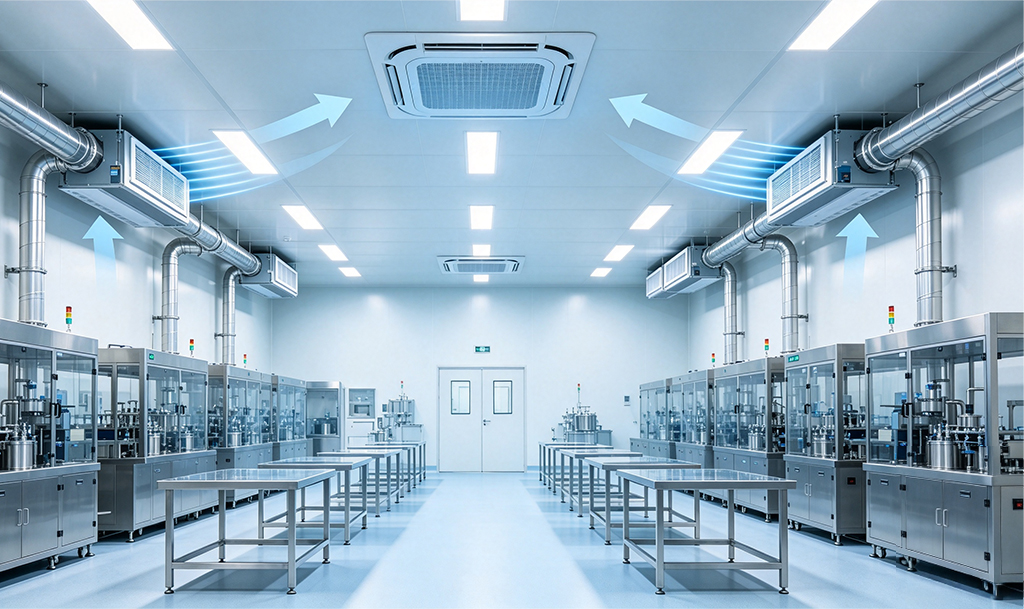
Most cleanroom airflow systems get validated under empty or static conditions, but the moment operators step in and equipment starts running, that carefully balanced unidirectional flow can turn into a recirculating mess. The problem isn't always the fan or filter; it's that real-world heat loads, moving people, and exhaust from tools create localized pressure differences that push air sideways or back into critical zones.
A common silent failure is when return air grilles are placed too close to supply diffusers, causing short-circuiting. Instead of sweeping particles away from the product, the clean air takes the path of least resistance and leaves the room without ever reaching the work surface. Another issue is low air changes per hour combined with high particle release from operators, which makes the recovery time after a disturbance far longer than the design spec suggests. If you see unexplained particle counts near a specific workstation, the airflow pattern itself may be channeling contamination rather than protecting it.
Filter Choices That Matter More Than a Single MERV Number
Most people grab a filter based on the MERV number alone, but that single digit hides a lot of real-world nuance. A filter can boast a high MERV rating yet perform poorly if its media is flimsy or the frame leaks around the edges. What actually matters is how well the filter holds up under airflow, whether it seals tightly in the housing, and if the material resists collapsing or bypass. These factors often matter more than chasing the next rating point.
Another overlooked aspect is the balance between filtration efficiency and airflow resistance. A filter with an impressive MERV number might choke your system, forcing the blower to work harder and driving up energy use. In many cases, a slightly lower MERV filter with deeper pleats and lower pressure drop will do a better job over its lifespan. It keeps air moving while still capturing the particles you care about—without turning your HVAC into a wheezing mess.
Then there's the question of what you're actually trying to remove. MERV is a broad-spectrum rating; it doesn't tell you if a filter excels at grabbing fine dust, pet dander, or smoke. Some filters with the same MERV number perform quite differently depending on the fiber blend or charge treatment. Instead of fixating on one number, look at the filter's construction, the pleat density, and whether the manufacturer provides performance data for specific particle sizes. That's where the real choice lives.
Balancing Pressure Differentials Without Overcomplicating the Design
Pressure differences rarely demand a complex fix. A simple bypass channel or a well-placed vent can often handle minor fluctuations before they turn into seal wear or drift. The trick is to map where pressure builds during actual use, then add just enough relief capacity to keep the gradient stable.
Overdesign usually creeps in when every edge case gets its own feature. Instead, pick one primary relief path and size it for the most common peak, not the theoretical worst case. This keeps the assembly easier to machine, test, and maintain without sacrificing the core function.
Small details like orifice placement and surface finish tend to matter more than adding redundant valves. By focusing on the geometry that influences flow, you can keep the differential in check with fewer parts and less tuning.
Humidity Control Is an Overlooked Sterility Threat
Most cleanroom protocols obsess over particle counts, air changes, and gowning discipline, yet ambient moisture often slips through unnoticed. When relative humidity drifts above 60%, surfaces that appear dry can still harbor microcondensation, creating a silent breeding ground for mold, bacteria, and biofilm. Operators rarely connect a sudden spike in environmental monitoring excursions to a faulty humidifier or a poorly sealed steam line, but the correlation is often undeniable. Sterility isn't just about what you filter out; it's also about what you inadvertently invite in through the air itself.
Low humidity poses its own insidious risks. Below 30% RH, static electricity builds on gloves, vials, and conveyor belts, attracting particles that would otherwise settle harmlessly. More critically, desiccated droplets from sneezes or spills can aerosolize into respirable nuclei, bypassing HEPA filtration in turbulent zones. Aseptic filling lines in particular suffer from this yo-yo effect: too much moisture encourages growth, too little turns every movement into a particle dispersion event. The sweet spot is narrow, and drifting outside it quietly compromises the very sterility assurance level you've spent millions to maintain.
The fix isn't glamorous, but it's straightforward. Dedicated humidity sensors need to be placed at workbench height, not just in return ducts, and their data should trigger alarms alongside temperature and pressure excursions. Periodic checks of steam traps, cooling coil drains, and door seals matter as much as any SOP revision. When a batch fails sterility and no obvious breach is found, the humidity log is often the last place anyone looks—and the first place that should have been checked.
Air Change Rates Are a Starting Point, Not a Guarantee
Ventilation specs often get treated like a finish line. You’ll see a target air change rate in a project brief and assume hitting that number means the space is safe or healthy. In practice, that figure is more of a rough benchmark. It doesn’t account for how air actually moves through the room, where people sit, or whether the supply and exhaust create short-circuits that leave dead zones.
The same air change rate can behave completely differently depending on the layout. A high rate won’t help much if the fresh air dumps into an empty corner and gets pulled out before it ever reaches the occupied zone. Meanwhile, a lower rate with smart displacement or well-placed diffusers can keep contaminants lower where it matters. That’s why measuring only the volume of air exchanged per hour gives you an incomplete picture.
Treat the air change rate as a starting point for design, not a final answer. Look at where the air goes, how the space is used, and what you’re actually trying to dilute or remove. Then adjust your setup and verify with measurements in the breathing zone. If you stop at the stated rate, you may check a box on a form but miss the real goal.
Sensor Placement That Catches Cleanroom Drift Before It Spreads
Cleanroom drift rarely announces itself. The first signs are often small: a slight pressure reversal near a pass-through, a temperature rise in one corner, or an unsteady particle count downstream of a gowning area. Placing sensors only in the geometric center of a room misses these early warnings. Instead, the most useful locations are at points where air changes direction or slows down—near return air grilles, around equipment that sheds heat or particles, and just beyond high-traffic doorways. These are exactly the places where drift begins before it migrates into the main airflow.
A practical placement strategy treats the cleanroom as a set of micro-zones rather than one uniform space. Sensors should bracket the critical process, not just hover above it. For example, one sensor positioned upstream of a filling line and another downstream can reveal whether the clean air is actually sweeping contaminants away or simply pushing them toward the product. Adding a sensor at the return air path gives an early indication of filter loading or pressure imbalance, often hours before a room-wide alarm triggers.
The goal is to catch drift at its origin, not after it has mixed into the entire volume. Placing sensors near potential sources—doorways, material transfer hatches, maintenance access panels—turns them into tripwires. When those tripwires record a deviation, the operations team can adjust airflow or defer a non-essential entry before the drift reaches the product. This approach reduces false alarms caused by distant, already-mixed readings and makes the monitoring data directly useful for root cause analysis.
FAQ
Cleanroom HVAC focuses on controlling particle counts, pressure cascades, temperature, humidity, and airflow patterns to protect processes, not just occupant comfort. It relies on high-efficiency filtration, precise air change rates, and controlled airflow direction to sweep contaminants away from critical zones.
Air change rates should be calculated from the required cleanliness class defined by ISO 14644-1, internal particle generation from equipment and personnel, and heat loads. Instead of using a fixed rule-of-thumb, derive the required airflow from particle concentration limits and add a safety margin for recovery time after contamination events.
Pressure cascade keeps air moving from cleaner to less clean spaces, preventing contaminated air from entering through door gaps or openings. Typical differentials are 10-15 Pa positive for ISO 7/8 rooms, with higher values for stricter classes, but actual settings must account for door operation and building envelope leakage.
Humidity affects static electricity, microbial growth, corrosion, and comfort for gowned workers. A common target is 45-55% RH, though some processes need tighter bands. Using a dedicated outdoor air unit with dew point control is more reliable than terminal reheat alone, especially in humid climates.
Use staged filtration: pre-filters rated MERV 8-13 protect HEPA or ULPA final filters from premature loading, and final filters should be placed at the point of air entry to the cleanroom to avoid downstream re-contamination. Integrity testing and pressure drop monitoring are both necessary for ongoing performance.
For ISO 5 and cleaner zones, unidirectional flow is essential, typically vertical at 0.3-0.5 m/s from ceiling to floor. In ISO 7/8 spaces, turbulent mixed flow with high air change rates and strategic supply/return placement can work, but critical tasks should be protected by local unidirectional flow hoods.
Oversizing cooling coils for future flexibility often leads to poor humidity control at part load. Ignoring return air grille placement creates dead zones where particles accumulate, and failing to account for process exhaust can disrupt pressure balance. Detailed air balancing and commissioning catch many of these issues before operation.
Use variable air volume on non-critical zones, optimize air change rates through risk assessment rather than fixed rules, recover heat from exhaust air, and select high-efficiency fans and motors. Airflow setback during idle periods is possible if validated that cleanliness recovers quickly, but pressure cascades and filter integrity must never be compromised.
Conclusion
Cleanroom HVAC design rarely fails because of a single bad component—it fails when the system’s assumptions stop matching how air actually moves. A laminar-flow scheme that looks perfect on paper can create dead zones if equipment placement or personnel movement disrupts the unidirectional stream, leaving particles to linger exactly where sterility matters most. The fix isn't always more airflow; it's rethinking return-air locations and using smoke studies or CFD early enough to catch recirculation loops. Filter selection adds another layer: chasing a higher MERV rating ignores that pressure drop, media loading behavior, and leak integrity at the housing often determine real-world performance more than a single number. Specifying a filter that holds its rated efficiency through the expected loading cycle keeps a cleanroom stable far longer than swapping in the highest MERV option available. Pressure differentials then become easier to manage when you stop treating them as a standalone goal. Instead of cascading pressure gradients that create noisy doorways and constant hunting by the controls, design the envelope and ductwork to minimize leakage paths, then let modest offsets—typically 10–15 Pa between adjacent classes—do the work without overburdening the fans.
Humidity control is where many cleanrooms quietly lose their sterility edge. If relative humidity drifts above 60%, condensation on cold surfaces invites biofilm formation and makes particles stick to gowns and gloves; below 30%, static discharge can disrupt sensitive processes and attract particulate. Tight humidity bands require thoughtful dehumidification and humidification sequencing, not just a setpoint on a BMS screen. Air change rates offer a similar illusion of safety: 60 air changes per hour may satisfy a guideline but still leave contamination if the supply air doesn't sweep the critical zone. Treat ACH as a starting point, then verify recovery time after a smoke challenge or particle release. Finally, sensor placement decides whether you catch drift before it spreads. A single particle counter near the return grille can miss a localized release at a filling line; placing sensors at operator breathing height, near transfer hatches, and downstream of critical operations gives you early warning, allowing adjustments before a batch is compromised. Together these strategies shift cleanroom HVAC from code compliance to true process protection.
Contact Us
Contact Person: Amy Yang
Email: [email protected]
Tel/WhatsApp: 008619330882686
Website: https://www.genopharmatech.com/