

Custom Megasonic Cleaning Systems: How to Achieve Sub-Micron Particle Removal
2026-10-03
If you've ever pushed a cleaning process below the micron level, you know that standard ultrasonic tanks stop being effective just when precision matters most. Particles smaller than the wavelength of the agitation simply refuse to budge. Custom megasonic cleaning systems change that by matching frequency, power density, and fluid dynamics to your exact part geometry. In this article, we break down how Siansonic engineers tackle sub-micron particle removal—and why a one-size-fits-all approach usually fails.
Why Standard Megasonic Setups Fall Short for Sub-Micron Particles
Most standard megasonic cleaning systems operate at a fixed frequency, typically around 1 MHz, and apply continuous, uniform power across the entire bath. This creates a standing wave pattern where nodes and antinodes form, resulting in uneven acoustic energy distribution. Sub-micron particles, which cling to surfaces with relatively weak van der Waals forces, often reside in low-energy zones where the acoustic pressure is insufficient to dislodge them. The fixed frequency also ignores the fact that different substrate regions and particle types respond better to varying acoustic conditions, leaving a significant fraction of tiny contaminants untouched.
Another limitation stems from the mismatch between cavitation bubble size and particle dimensions. Standard setups generate relatively large transient cavities, and their collapse produces shockwaves and microjets that are effective for removing particles in the micron range. However, sub-micron particles are so small that these energetic events often sweep right past them without transferring enough momentum. The bubbles can even encapsulate the particles, but upon collapse, the released energy is diffuse rather than focused, failing to break the adhesive bonds that hold sub-micron debris to the surface.
The viscous boundary layer near the substrate presents an additional hurdle. Within this thin layer, fluid motion is severely damped, and acoustic streaming velocities drop dramatically. Since sub-micron particles sit almost entirely inside this boundary layer, they experience very little drag force from the bulk liquid flow. Standard megasonic systems lack the frequency modulation or pulsed operation needed to compress the boundary layer or generate localized turbulence, so these tiny particles remain shielded from the cleaning action, resulting in low removal efficiency for the most stubborn residues.
Matching Transducer Arrays to Your Part Geometry
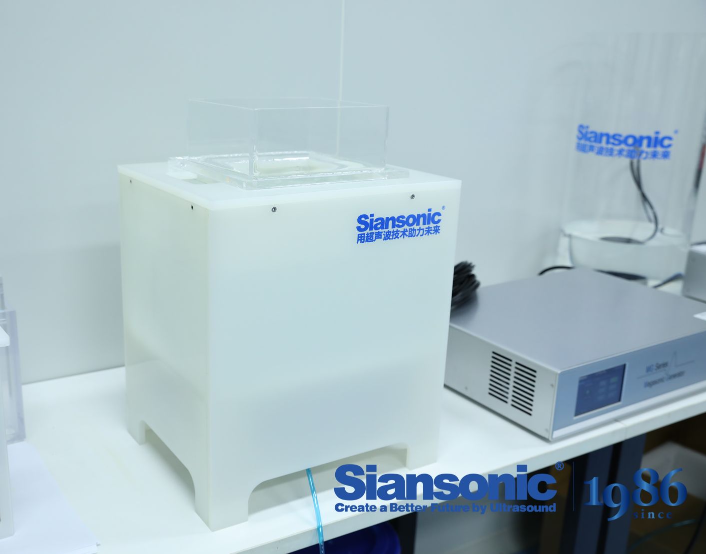
Part geometry rarely cooperates with off-the-shelf transducer designs. A flat linear array may scan a simple plate without issue, but once the surface curves, tapers, or steps, the acoustic coupling and beam steering assumptions collapse. The first step in matching an array to your part is mapping the inspection surface: note the minimum radius of curvature, wall thickness transitions, and any features like threads, weld caps, or fastener holes that block access. For concave or convex surfaces, a flexible array or a rigid array mounted in a custom contoured wedge can maintain a consistent standoff and avoid air gaps that kill signal strength. Pay particular attention to the active aperture length—too long and the array bridges across high spots, losing contact at the edges; too short and you sacrifice focusing capability at depth.
For cylindrical components such as pipes and pressure vessels, curved arrays or shaped wedges let you align the beam normal to the surface while still steering electronically along the circumference. A common trick is to machine a wedge from the same nominal radius as the part, then use a linear array with a modest number of elements to cover the weld zone without excessive refraction errors. On highly irregular geometries—think turbine blade roots, valve bodies, or additive-manufactured brackets with internal channels—a matrix array often outperforms a linear array because it can steer in two planes simultaneously and adapt to local contour changes without mechanical repositioning. In some cases, a small immersion or water-column setup with a focused transducer can decouple the probe from the surface entirely, but that adds complexity and may not be practical in the field.
Before committing to a custom array, run beam simulations with the actual CAD model of the part. Look for coverage gaps near steep transitions or areas where the refracted angle shifts beyond the useful range for your material. Adjust element pitch to avoid grating lobes and confirm that the focal laws can generate the required angles across the entire region of interest. A quick validation on a mock-up with artificial reflectors will reveal whether the array truly hugs the geometry or just looks good on paper. When the array fits the part, you usually see better signal-to-noise, more uniform sensitivity, and far fewer false calls from geometry echoes.
Frequency Tuning Beyond the 40 kHz Default
Most ultrasonic systems ship with 40 kHz locked in because it covers a broad range of everyday tasks without much thought. But once you move past that preset, the behavior changes in ways that aren't always obvious. Lower frequencies, say 20 to 30 kHz, create larger cavitation bubbles and more aggressive cleaning or cutting action. Higher frequencies, around 60 to 120 kHz, produce gentler, finer effects that work better for delicate surfaces or precision dispersion.
The real value of tuning comes from matching the frequency to the physical properties of the material you're working with. A thicker, denser load often responds better to a lower frequency that can carry more mechanical energy through the medium. Thin films or small particles, on the other hand, tend to respond to higher frequencies where the wavelength is shorter and the energy distribution is more uniform. Pushing beyond the default isn't just about more or less power; it's about changing how the energy interacts at the interface.
In practice, this means experimenting with the generator's sweep range or swapping transducers to find the point where cavitation noise drops and the process becomes visually steadier. Some setups benefit from a narrow sweep around an alternate center frequency, while others need a wider band to avoid standing waves. The 40 kHz default is a reasonable starting point, but the best results usually come from treating it as one setting among many rather than a fixed rule.
Chemistry Choices That Loosen Particles Without Damage
Most damage during particle removal comes from aggressive pH swings or solvents that attack the substrate faster than they break the particle bond. A safer route pairs a mild chelating agent—such as citrate or EDTA—with a nonionic surfactant. The chelator grabs metal ions at the particle-substrate interface, shrinking the adhesion force, while the surfactant lowers surface tension so the loosened particle can be rinsed away without abrasive scrubbing.
For oxidatively sensitive surfaces, replacing strong oxidizers with enzyme-based or buffered percarbonate blends can produce the same release effect without etching. The real judgment call is matching the chemistry to the particle type: mineral dust responds to slightly acidic or chelating formulas, whereas organic residues often need a targeted enzyme or a short-chain alcohol to weaken hydrophobic binding. A swab test on an inconspicuous area—not a full soak—shows whether a candidate solution will loosen debris or attack the surface.
Particle size also drives formulation choices. Submicron particles cling through van der Waals forces that ordinary rinsing cannot overcome, so a low-foam surfactant with good wetting ability is often more effective than a harsh alkaline cleaner. Adding a small amount of a polar aprotic solvent can further reduce interfacial tension, letting the chemistry slip beneath the particle and lift it off intact. This layered approach usually cleans faster and leaves the original finish untouched.
Validating Removal Efficiency with Real Particle Counts
Lab benchmarks only tell part of the story. To know whether a filtration system actually performs under real operating conditions, you need to count particles in the air stream before and after the unit—not just rely on theoretical efficiency curves or manufacturer spec sheets. A handheld optical particle counter placed upstream and downstream of the filter gives you a direct, side-by-side comparison of particle concentrations across key size channels, typically 0.3, 0.5, 1.0, 2.5, 5.0, and 10.0 microns. The removal efficiency at each size is then calculated as one minus the downstream-to-upstream concentration ratio, expressed as a percentage.
What often surprises people is how variable real-world counts can be. Doors opening, nearby traffic, HVAC cycling, even the movement of occupants can cause short-term spikes that skew a quick measurement. That is why a single grab sample rarely provides a reliable efficiency number. Instead, you log data continuously for at least 15 to 30 minutes, then compare medians or time-weighted averages rather than instantaneous readings. The goal is to capture the system's steady-state performance while acknowledging that transient events are part of normal operation.
One practical tip: always zero or purge the particle counter between measurement locations, and keep sampling probe lengths identical to avoid tubing losses for larger particles. If the downstream count is too low to register on a standard optical counter—say, below 10 particles per cubic foot at 0.3 microns—switch to a condensation particle counter or extend the sample time. Otherwise you risk dividing by near-zero upstream numbers and generating an artificially high efficiency that has little meaning in the field.
Preventing Cavitation Erosion While Keeping Cleaning Power
Cavitation erosion and cleaning power both live on the same violent edge, so the trick isn't to dial back intensity across the board—it's to shape where and how those collapsing bubbles do their work. A fixed-frequency generator tends to hammer the same microscopic zones over and over, quickly pitting softer metals or delicate coatings. Switching to a swept-frequency system, even a narrow band of ±1–2 kHz, spreads the bubble collapse sites across a wider area and breaks up standing waves that otherwise create hot spots on the part. The result is a more even scrubbing action that removes contamination without letting any single point absorb all the mechanical punishment.
Chemistry and temperature give you another lever. Running the bath at the upper end of the detergent's recommended range lowers surface tension and softens soils, which means you can reduce ultrasonic power while still hitting the same cleaning benchmark. Degassing the liquid before loading parts also matters more than it seems—dissolved air cushions bubble implosions at first, so operators often crank up the amplitude to compensate. Once the gas is gone, that same amplitude becomes overly aggressive. A short degas cycle at full power, followed by a drop to the working level, protects fragile substrates without sacrificing throughput.
Finally, part placement and pulse timing can preserve both the workpiece and the production schedule. Rotating or repositioning the component so that critical surfaces don't sit directly over a transducer face reduces focused erosion. If your equipment supports variable pulse modes, a brief on/off cadence allows the bath to refresh and prevents the formation of persistent low-pressure zones that dig into metal. The goal isn't gentler cleaning—it's smarter energy distribution, so the same wattage removes grime efficiently but leaves the substrate intact.
FAQ
Megasonic uses higher frequencies around 1 MHz or more, producing gentler cavitation and controlled acoustic streaming. That prevents damage to delicate surfaces while still dislodging particles far smaller than a micron. Ultrasonic, by contrast, operates at lower frequencies with more violent bubble collapse, which can pit substrates or leave residues.
Off-the-shelf units are built around generic tank geometries and fixed transducer layouts. Custom engineering matches the acoustic field to the specific part shape, material, and contamination profile. This alignment reduces dead zones and standing-wave nulls, so the cleaning energy reaches every recess where sub-micron particles hide.
Frequency, power density, temperature, and chemistry all interact. Higher frequency helps with smaller particles, but power must be tuned to avoid bubble implosion damage. Temperature changes viscosity and gas solubility, shifting cavitation thresholds. Matching the chemistry to the particle's surface charge prevents reattachment after lift-off.
Use a known challenge wafer or test coupon contaminated with particles of a controlled size, then count defect maps before and after cleaning. Scanning electron microscopy or atomic force microscopy confirms removal efficiency down to 0.1 micron or below. Repeated runs under identical conditions show whether the result is stable or just a lucky pass.
Transducer placement defines the acoustic pattern inside the tank. Poor placement creates interference bands where energy is weak, leaving particles untouched. Custom placement models the part's geometry and positions transducers so the sound field overlaps evenly across critical surfaces, turning standing waves into uniform cleaning action.
Yes, if the acoustic energy is delivered gently. Megasonic frequencies allow particle removal without the harsh cavitation found in ultrasonic baths. Combined with a tailored temperature ramp and low chemistry concentration, it lifts sub-micron particles from polymers, thin films, or fragile MEMS structures while preserving material integrity.
Treating frequency as a single magic number, ignoring the tank's acoustic impedance, or overdriving power to compensate for dead zones. Another mistake is neglecting filtration and rinse quality. Particles removed from the surface can redeposit if the bath is not continuously conditioned, so the system needs integrated particle control, not just more sonic energy.
Acoustic streaming creates steady, small-scale fluid motion near the substrate surface. This flow drags particles out of the boundary layer where they adhere. Because the streaming force drops rapidly with distance, the effect is confined to the surface, making it ideal for displacing sub-micron debris without disturbing bulk fluid or causing particle redeposition.
Conclusion
Standard megasonic cleaning rigs tend to stumble below the sub-micron threshold because a single 40 kHz transducer array assumes a flat, uniform surface. Real parts have pockets, through-holes, and stepped geometries that scatter acoustic energy unevenly. A custom setup maps emitter positions to the actual contour, blanketing recessed areas while avoiding hot spots. Frequency tuning plays an equally large role: stepping through a narrow band around one or two megahertz—rather than staying locked at the default—helps dislodge particles that are held by van der Waals and electrostatic forces, without pushing the system into aggressive transient cavitation. Paired with chemistry selected for the specific film and particle type, the liquid can weaken adhesion without attacking the substrate.
Verification changes everything. Instead of relying on water-break tests or casual microscopy, robust programs count particles before and after cleaning using liquid optical particle counters or membrane collection with SEM review. Those real numbers expose blind spots in nozzle placement or insufficient soak time. At the same time, erosion must be kept in check: degassing the process fluid, limiting acoustic intensity, and modulating duty cycle preserve cleaning power while preventing pitting on delicate features. The result is a controlled acoustic field, matched chemistry, and measurable removal—so that sub-micron cleanliness becomes a repeatable output rather than an occasional accident.
Contact Us
Contact Person: Ivy Zhang
Email: [email protected]
Tel/WhatsApp: +86 1081502288
Website: https://www.siansonic.com/