

Best 3 Axis Milling Center Options for Precision Machining
2026-09-04
Finding a 3-axis milling center that holds tight tolerances without constant babysitting isn’t a given—many machines drift when the spindle heats up or the table gets loaded unevenly. For shops chasing repeatable precision machining results, the right build quality and control system matter more than a spec sheet full of promises. In this guide, we cut through the noise and lay out the strongest options on the market, including why WINNRUI CNC keeps showing up in shortlists for shops that can’t afford scrap parts.
Why Box Ways Still Beat Linear Rails for Heavy Precision Cuts
When a spindle buries a large face mill into a cast iron bed plate, the cutting forces don't just push back—they twist, bounce, and vibrate through every joint in the machine. That's where box ways earn their keep. The massive sliding contact area of a box way, often hand-scraped to fit, creates a mechanical averaging effect that linear rails simply can't match. Instead of relying on rows of small recirculating balls, the entire carriage rides on broad, flat iron surfaces with a film of way oil in between. This turns the interface into a high-damping, high-stiffness connection that soaks up chatter before it reaches the part.
Linear guides are great for speed and low friction, but their point contact geometry means local deformation under heavy load. Under a deep cut with a large tool overhang, those tiny contact patches can deflect, causing the tool to micro-wander and leave a wavy finish. Box ways, by contrast, spread the load over square inches, not square millimeters. The result is a cutting platform that stays put when you push it hard. Add to that the ability to run tight gibs or hydrostatic pressure for even more preload, and you get a machine that can hog material all day without losing dimensional accuracy.
Of course, box ways are not perfect for every job. They demand more attention to lubrication, are slower to rapid, and can develop stick-slip at low speeds if not properly maintained. But for those heavy, interrupted cuts in tough alloys—where a linear rail machine would start singing and leave a chatter pattern like a vinyl record—a box way machine just keeps cutting clean. It's the difference between a sports car and a bulldozer. You don't use a bulldozer for a lap time, but you don't ask a sports car to rip out a foundation.
The 15,000 RPM Spindle Myth in Tight-Tolerance Work
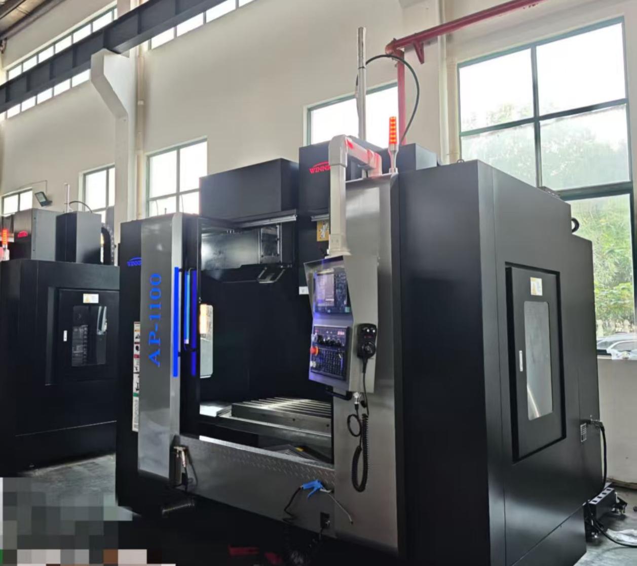
There's a persistent notion in job shops that hitting 15,000 RPM on the spindle is a prerequisite for holding a tight tolerance. The logic seems straightforward: faster spindle means faster material removal, which should mean more precise finishes. But in practice, that speed often introduces more error than it eliminates. Bearing heat, micro-vibration, and harmonics start to stack up quickly when the spindle is screaming, and those tiny disturbances translate directly into out-of-round bores or surface finish variations you'd never see at 10k.
What actually matters for tight-tolerance machining is stability and thermal control. A spindle spinning at 15k generates significantly more heat in the front bearings than at 8-10k, and that thermal growth can shift your tool tip by several microns before the control compensates. Add in cutter imbalance or a slightly worn holder, and the resulting vibration will carve a finish that no amount of spindle speed can fix. The most accurate shops often run at moderate RPM with balanced tool assemblies, rigid workholding, and sharp tools that shear rather than rub.
Plenty of high-precision parts come off machines that never exceed 12,000 RPM, and some of the tightest bore work is done under 6,000. The myth persists because spindle speed is easy to measure and impress, while rigidity, runout, and thermal equilibrium are harder to see. But the next time a tight tolerance slips, the fix usually isn't more RPM—it's a better toolpath, a shorter gauge length, or a proper warm-up cycle. Let the spindle speed be dictated by the material and cutter geometry, not by a marketing number.
Squeezing Maximum Work Envelope from a Compact 3-Axis Footprint
The phrase "squeezing maximum work envelope from a compact 3-axis footprint" points to a design challenge in precision motion systems. Rather than simply scaling up frame rails, engineers reclaim travel by overlapping axis strokes, shifting the tool center point closer to the front edge, and removing redundant bearing blocks. The result is a work cube that can exceed 60% of the machine's outer dimensions on all three axes without adding shop-floor bulk.
A common trick is to mount the Z-axis carrier behind the X-axis saddle instead of below it, letting the spindle nose reach the table's near edge while the counterweight and linear guides stay inside the base casting. Pair that with a Y-axis bridge placed at the rear of the column, and you avoid the dead zone under the gantry legs. This arrangement keeps the tool path envelope rectangular and pushes usable strokes to about seventy percent of footprint length and width.
Thermal stability and cable routing often eat into the final numbers. Using a moving-column design with the ballscrew centered between the rails reduces lost travel at stroke ends, while a service loop routed through the column hollow avoids snag points that would otherwise force software limits. These small integration choices add up to extra millimeters that matter when a part barely fits the vise.
Thermal Drift Is the Real Enemy of All-Day Dimensional Accuracy
Most shops treat temperature as a background condition—something to note but not actively fight. Yet thermal drift doesn't announce itself. A spindle warms up, a granite table expands unevenly, and a part that measured dead-on at 9 a.m. has drifted by three microns before lunch. It's rarely a single dramatic shift; it's a slow creep that accumulates across hours, hiding inside otherwise stable processes.
The real problem is that drift mimics other errors. You might chase tool wear, fixture looseness, or probing inconsistency when the actual culprit is a five-degree rise near a window or a heat source cycling on and off. Materials don't grow at the same rate—aluminum moves differently than steel, and composites can be worse. If your reference frame and your workpiece expand at different speeds, every measurement inherits that mismatch.
Fighting thermal drift means designing for it before it bites. Warm-up cycles, thermal compensation in software, and strategic placement of temperature sensors help, but the biggest gains come from choosing materials with matched coefficients and isolating heat sources from metrology loops. Some shops even map drift over a full shift and feed that data back into offsets. The point isn't to eliminate temperature change—that's impossible—but to know exactly how your system bends when it heats up, and correct for it before the tolerance window closes.
One Mill for Aluminum, Stainless, and Inconel Without Constant Retuning
Running aluminum, stainless, and Inconel on the same mill usually means chasing feeds, speeds, and chatter from one job to the next. This machine was set up to break that cycle. The spindle, frame, and damping are tuned to hold tolerances across a wide stiffness range, so switching from gummy 6061 to a tough nickel alloy doesn't force a full retune. You adjust the recipe, not the machine itself.
What makes that possible is a combination of a stiff cast base, preloaded linear guides, and a spindle with enough torque at low RPM for Inconel while still reaching high RPM for aluminum finishing. Instead of relying on a single sweet spot, the control maps acceleration and jerk limits per material group. That means the same toolpaths run predictably across alloys, and the operator isn't constantly fighting resonance or tool wear spikes.
In practice, shops use one setup for a family of parts that mix materials. The mill holds size on an aluminum housing in the morning and a stainless bracket in the afternoon without backtracking on parameters. It reduces the need for separate roughing and finishing passes to compensate for machine flex, and it keeps surface finish consistent enough that secondary deburring drops noticeably.
What a 50-Taper Spindle Actually Changes on the Shop Floor
A 50-taper spindle brings a level of rigidity that’s immediately obvious when an end mill buries itself in steel. The tool doesn’t chatter or deflect the way it might in a 40-taper machine, so you can push feed rates up without watching the finish go to hell. That extra stiffness also means fewer random tool failures and less time spent tweaking offsets.
On the floor, the biggest difference shows up in long-reach and heavy roughing jobs. Face mills, big indexable drills, and large taps all run more predictably because the spindle resists the bending forces. Operators stop babying the machine and start trusting the programmed speeds and feeds, which cuts cycle times on parts that used to need multiple light passes.
There’s a downside, though—the toolholder inventory changes. You can’t reuse all your CAT40 or BT40 holders, and the toolchanger arms often need different grippers. But shops that do a lot of stainless, titanium, or hard milling find the swap worth it because the spindle bearings last longer and the scrap rate drops. That’s the kind of change you notice in the weekly numbers, not just the spec sheet.
FAQ
The biggest differences come down to thermal stability, way construction, and how well the control manages small moves. Look for machines with either hand-scraped box ways or high-grade linear rails that are preloaded properly. Spindle growth from heat is often the silent killer of tight tolerances, so core-cooled spindles or at least a good warm-up cycle matter. Also, the servo tuning needs to be crisp without overshoot, or you'll see scalloping on fine contours.
DMG Mori, Mazak, and Okuma are solid starting points if the budget allows. Haas and Hurco have come a long way for shops that need dependable precision without the premium price tag. Doosan also deserves a mention for how rigid their castings feel for the money. What matters more than the badge is how the machine is optioned—look for linear scale feedback or at least a well-tuned pitch error compensation map.
For most precision work, a high-speed spindle is only beneficial if you're using small tools on softer materials. What you actually need is low runout at the nose and consistent torque across the range. A 12,000 RPM spindle with a Big Plus dual-contact interface will often outperform a 20,000 RPM spindle with a standard 40-taper when it comes to holding size on reamed holes or interpolated bores.
You can get into a well-optioned 40x20 inch machine from a reputable builder for around $80,000 to $120,000 new. Adding probing, through-spindle coolant, and higher accuracy mapping will push it to $130,000 or more. Used machines from the premium Japanese builders can be a great value, but factor in a full ballbar test and possible ballscrew replacement so you don't inherit someone else's worn-out geometry.
The Mazak VCN series and DMG Mori CMX line are both known for blending power with finesse. The Haas VF-2SS is more forgiving on the wallet and does well when you stay within its horsepower envelope. If you deal with a lot of hardened steel or tough alloys, the Okuma Genos M560-V is hard to beat because its spindle stays composed under heavy cuts without losing finish quality.
Consistent spindle warm-up cycles are non-negotiable, especially in shops without climate control. Check and adjust the leveling every six months, because a settling foundation will twist the casting and throw off squareness. Keep way covers and wipers clean so abrasive fines don't work their way into the linear rails. Finally, run a ballbar test once a year to catch early signs of backlash or servo mismatch before scrap parts expose it.
For precision machining, yes on both counts, but for different reasons. Linear scales give you direct feedback on table position, which removes thermal drift from ballscrew growth and is huge for holding tolerances under varying shop temperatures. Probing won't make parts more accurate by itself, but it lets you verify setups and in-process dimensions quickly, reducing human error and allowing you to correct drift before it becomes a problem.
Conclusion
Shops chasing true precision on a 3-axis mill quickly discover that the stiffest, most thermally stable foundation often beats a spec sheet full of spindle speed. Box ways, for all their old-school reputation, still deliver the damping and contact area needed when a heavy cut in stainless or Inconel tries to chatter a machine off its pads. A 15,000 RPM spindle sounds impressive, but tight-tolerance work rarely lives at top end; what matters more is torque at low RPM and a spindle that holds runout through long cycles. And that compact footprint you were worried about? A smartly designed column and table can give you a surprisingly deep work envelope without eating floor space—if you resist the urge to over-spec travels you won't actually use.
Then there's thermal drift, the quieter killer of all-day accuracy. Machines with core-cooled ballscrews, headstock symmetry, and warm-up routines will hold a few tenths long after a less-thoughtful mill has wandered. In mixed-material job shops, the right 3-axis platform should swing from aluminum to stainless to Inconel without constant pid tuning or feed-rate prayers; that comes down to rigid castings, balanced axis drives, and a control that lets you save proven parameter sets. Finally, if your work regularly calls for big face mills, long gage lengths, or deep reach, a 50-taper spindle changes the conversation entirely—more drawbar force, less tool droop, and cuts you simply wouldn't dare with a 40-taper. None of these are headline features, but together they separate a machine that prints money from one that just moves.
Contact Us
Contact Person: Tim
Email: [email protected]
Tel/WhatsApp: +86 15522553731
Website: https://www.winnrui-cnc.com/